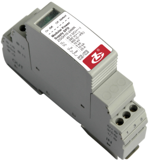
ZGGH10-24
General
ZGGH10-24 Modular Power Supply SPD consists of a power module and a base, used for the secondary or tertiary protection of + — - and - — PE of DC systems. It is connected between the DC power supply and system equipment in series or in parallel. It can prevent the equipment from the impulse surge and transient overvoltage caused by the outside environment (such as lightning, EMI, etc.) or by the system (such as switching effects of the system, startup or shutoff of the inductance and capacitance load, etc.).
Features
1Anti-reverse protection on the module;
2Low residual voltage;
3Overtemperature protection;
4Failure indication and centralized remote signalling alarm dry contacts;
5Enclosure IP20, UL94 V0.
Standards Complied
IEC 61643-11:2011 Low-voltage surge protective device-part 11: surge protective devices connected to low-voltage power systems-Requirements and test
EN 61643-11:2012 Low-voltage surge protective device-part 11: surge protective devices connected to low-voltage power systems-Requirements and test
Technical Data
Operating Environment
| Temperature |
-40℃~85℃ |
| Relative humidity |
5 %~95 % |
| Altitude |
-500 m~﹢4000 m |
Technical Parameters
| Model |
ZGGH10-24 |
| SPD according to IEC 61643-1 |
Class Ⅱ, Class Ⅲ |
| SPD according to EN 61643-11 |
Type 2, Type 3 |
| Max. continuous operating voltage Uc |
+— -:45 V DC;-—PE:0 V |
| Nominal discharge current In (8/20μs) |
5 kA |
| Max. discharge current Imax (8/20μs) |
10 kA |
| voltage protection Up |
+ — -:280 V;- — PE:800 V |
| Compound wave Uoc |
10 kV |
| Rated load current IL |
25 A |
| Prepositioned fuse |
25 A gL/gG |
| Connection mode |
Series; Parallel |
| Protection mode |
+ - -;- - PE |
| Response time tA |
+ - -:≤25 ns; - - PE:≤100 ns |
| Cross-sectional area of connecting terminals |
Multicore: 0.2 mm2~2.5 mm2; single-core: 0.2 mm2~4 mm2 |
| Cross-sectional area of the remote signalling interface (max.) |
2.5 mm2 |
| Intensity of the remote signalling alarm contact |
AC: 250 V/0.75 A 125 V/3 A DC: 30 V/2 A |
| Torque: connecting terminal |
0.5 N•m |
| Enclosure degree of protection (IP code) |
IP 20 |
| Installation system |
DC system |
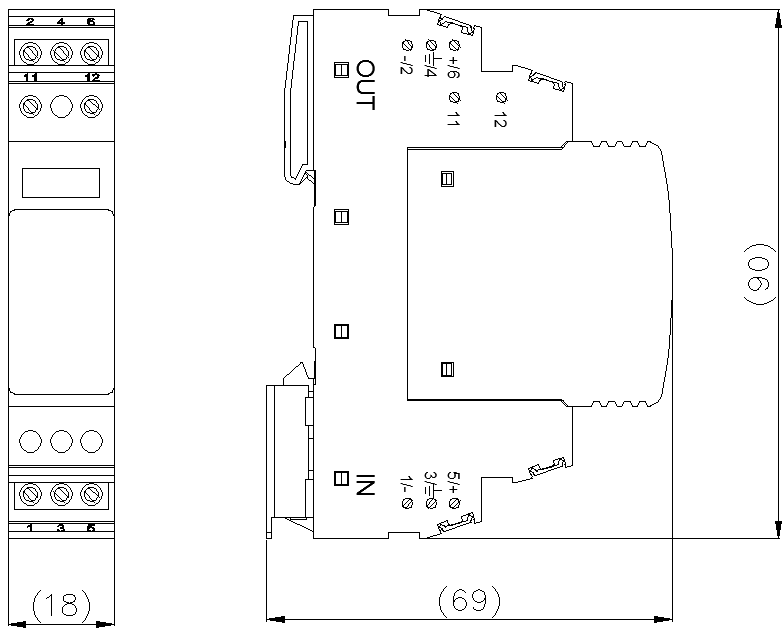
| Dimensions |
90 mm×18 mm×69 mm
(excluding remote signalling terminals) |
| Mounting on |
DIN 35 mm rail |
| Flammability |
UL 94 V-0 |
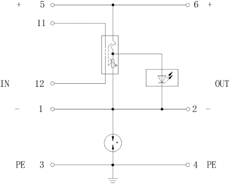
Circuit diagram
Configuration