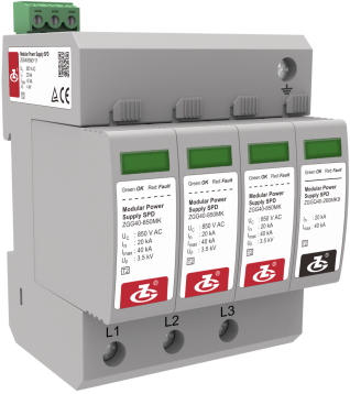
ZGG40-850(3+1)f
General
ZGG40-850(3+1)f is made up of three MOV power modules, one GDT power module and a base, used for secondary protection of L-PE.
Features
1Anti-reverse plug and anti-mutual insert.
2High discharge capacity, low residual voltage.
3Overtemperature protection.
4Failure indication and centralized remote signalling alarm dry contacts.
5Enclosure IP 20, UL 94 V-0.
Standards Complied
IEC 61643-11:2011 Low-voltage surge protective device-part 11: surge protective devices connected to low-voltage power systems-Requirements and test
EN 61643-11:2012 Low-voltage surge protective device-part 11: surge protective devices connected to low-voltage power systems-Requirements and test
Technical Data
Operating Environment
| Temperature range |
-40 ℃~﹢80 ℃ |
| Relative humidity range |
5 %~95 % |
| altitude range |
-500 m~﹢4000 m |
Technical Parameters
| Model |
ZGG40-850(3+1)f |
| SPD according to IEC 61643-11 |
Class Ⅱ |
| SPD according to EN 61643-11 |
Type 2 |
| Max. continuous operating voltage UC |
850 V AC |
| Operating frequency |
50/60 Hz |
| Nominal discharge current In (8/20μs) |
20 kA |
| Max. discharge current Imax (8/20μs) |
40 kA |
| Voltage protection level Up |
4.0 kV |
| Max. backup fuse |
80 A gL/gG |
| Connection mode |
parallel |
| Protection mode |
L-PE |
| Response time tA |
≤100 ns |
| Cross-sectional Area |
Stranded: 1.5 mm2~25 mm2, Solid: 1.5 mm2~35 mm2 |
| Max. Cross-sectional Area For Remote signalling terminals |
1.5 mm2 |
| Intensity of Remote Signalling Alarm Contact |
AC: 250 V/0.5 A 125 V/1 A DC: 30 V/0.1 A |
| Torque: Connecting Terminal/Remote Signalling Interface |
2.5 N•m /0.25 N•m |
| Degree of Protection (IP Code) |
IP 20 |
| Installation system |
TN、TT、IT |
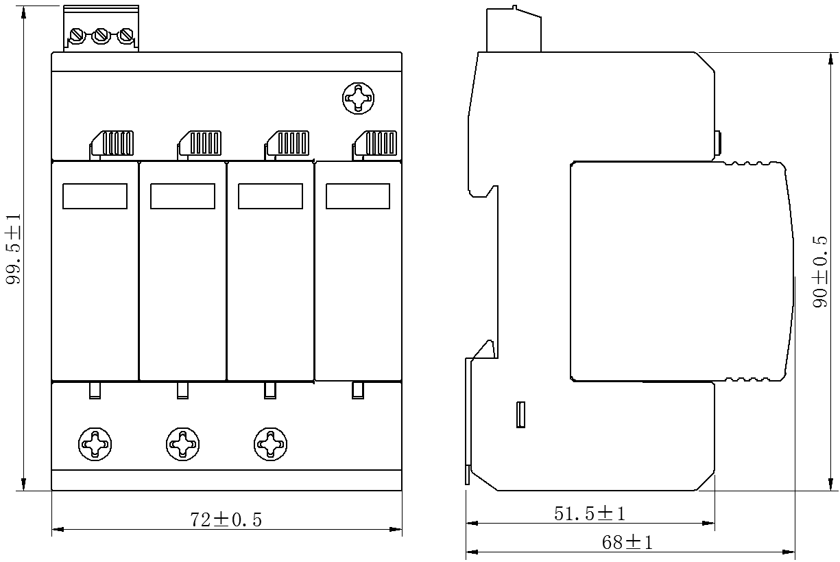
| Installation system |
90 mm×72 mm×68 mm (excluding remote signalling terminals) |
| Dimensions |
DIN 35 mm rail |
| Mounting on |
UL94 V-0 |
Circuit Diagram
Configuration