ZGGB40-385(4+0)
General
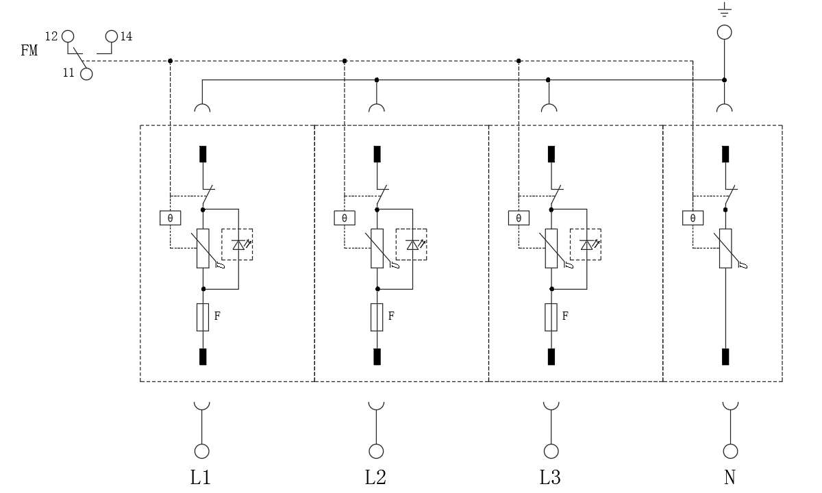
The ZGGB40-385(4+0) Modular Power Supply SPD is made up of MOV power modules and a base, used for secondary protection of L-PE、N-PE respectively. It applies in low voltage AC power distribution systems, and is connected between the AC power supply and the equipment in parallel. It protects the equipment from impulse surge and transient overvoltage caused by the outside environment (such as lightning and EMI) or by the system (such as switching effects of the system, startup or shutoff of the inductance and capacitance loads).
Features
1.Anti-plug and mutual-plug protection
2.No backup fuse needed
3.High discharge capacity, low residual voltage
4.Overheating and over-current protection
5.Failure indication and centralized remote signalling alarm dry contacts
Standard Complied
IEC 61643-11:2011 Low-voltage surge protective devices – Part 11: Surge protective devices connected to low-voltage power systems – Requirements and test methods
Technical Data
Operating Environment
| Temperature range |
–40°C to 80°C |
| Relative humidity range |
≤ 95% (25°C) |
| Altitude range |
–500 m to 4000 m |
Technical Parameters
| Model |
ZGGB40-385(4+0) |
| SPD according to IEC 61643-1 /11 |
Class Ⅱ |
| SPD according to EN 61643-11 |
Type 2 |
| Maximum continuous operating voltage Uc |
385 V AC |
| Working frequency |
50/60 Hz |
| Nominal discharge current In (8/20 μs) |
20 kA |
| Maximum discharge current Imax (8/20 μs) |
40 kA |
| voltage protection level Up |
2.0 kV |
| Access mode |
In parallel |
| Response time TA |
L/N-PE |
| Cross-sectional area of the copper wire connected by the terminal |
≤25 ns |
| Cross-sectional area of the copper wire connected by the remote signalling interface |
Multi-core wire: 1.5 mm2-25 mm2, single-core wire: 1.5-35 mm2 |
| Sensitivity of the remote signaling alarming contact |
0.5~1.5 mm2 |
| Torque: Terminal/Remote signalling interface |
AC: 125 V/0.5 A DC: 30 V/0.1 A |
| Degree of protection of enclosure (IP rating) |
2.5/0.25 Nm |
| Application system |
IP 20 |
| Access mode |
TN-S |
| Installation mode |
35-mm guide rail |
| Flammability |
UL94 V-0 |
Circuit Diagram
Configuration
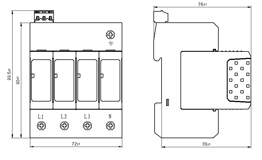
Dimensions (H x W x D): 90 mm x 72 mm x 76 mm (not including remote signalling interface)


