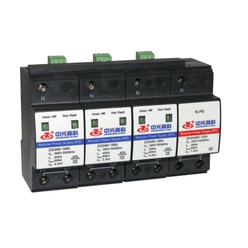
ZGG80/100/120 Series
General
This series is used for primary and secondary surge protection. The 3+1 and 1+1 configurations are composed of MOV and GDT power module for L-N, N-PE protection respectively. The 4+0 and 2+0 configurations are composed of MOV power module for L-PE, N-PE protection. It is applied in low voltage AC power distribution system, and connected between the AC power supply and the equipment in parallel. It can prevent the equipment from the impulse surge and the transient overvoltage caused by the outside environment (such as lightning, EMI, etc.) or by the system (such as switching effects of the system, startup or shutoff of the inductance and capacitance load, etc.).
Features
1High discharge capacity, low residual voltage.
2Overtemperature protection.
3Failure indication and centralized remote signalling alarm dry contacts.
4Enclosure IP 20, UL 94 V-0.
Standards Complied
IEC 61643-1:2005 Surge protective devices connected to low-voltage distribution systems-Part 1: Performance requirements and testing methods
GB 18802.1-2011 Low-voltage surge protective devices - Part 1: Surge protective devices connected to low-voltage power distribution systems- Requirements and tests
YD/T 1235.1-2002 Technical requirements for surge protective devices connected to low-voltage distribution systems of telecommunication stations/sites
YD/T 1235.2-2002 Testing methods for surge protective devices connected to low-voltage distribution systems of telecommunication stations/sites
Technical Data
Operating Environment
| Temperature |
-40 ℃~80 ℃ |
| Relative humidity |
5 %~95 % |
| altitude |
-500 m~﹢4000 m |
Technical Parameters
| Mode |
ZGG80-385(3+1)r |
ZGG100-385(3+1)r |
ZGG120-385(3+1)r |
| ZGG80-385(1+1)r |
ZGG100-385(1+1)r |
ZGG120-385(1+1)r |
| SPD according to IEC 61643-11 |
Class Ⅱ |
| SPD according to EN 61643-11 |
Type 2 |
| Protection mode |
L-N, N-PE |
| Max. continuous operating voltage UC |
385 V(L-N); 255 V(N-PE) |
| Operating frequency |
50/60 Hz |
| Nominal discharge current In (8/20μs) |
40 kA |
50 kA |
60 kA |
| Max. discharge current Imax (8/20μs) |
80 kA |
100 kA |
120 kA |
| Voltage protection level Up |
2.2 kV(L-N); 1.5 kV(N-PE) |
2.4 kV(L-N); 2.0 kV(N-PE) |
2.5 kV(L-N, N-PE) |
| Max. backup fuse |
250 A gL/Gg(L-N) |
315 A gL/Gg(L-N) |
400 A gL/Gg(L-N) |
| Follow current interrupt rating Ifi |
100 Arms(N-PE) |
| Response time tA |
≤25 ns(L-N); ≤100 ns(N-PE) |
| Connection mode |
parallel |
| Cross-sectional Area |
tranded: 1.5 mm2~25 mm2, Solid: 1.5 mm2~35 mm2 |
| Max. Cross-sectional Area For Remote signalling terminals |
1.5 mm2 |
| Intensity of Remote Signalling Alarm Contact |
AC: 250 V/0.5 A 125 V/1 A DC: 30 V/0.1 A |
| Torque: Connecting Terminal/Remote Signalling Interface |
2.5 N•m /0.25 N•m |
| Degree of Protection (IP Code) |
IP 20 |
| Installation system |
TN、TT |
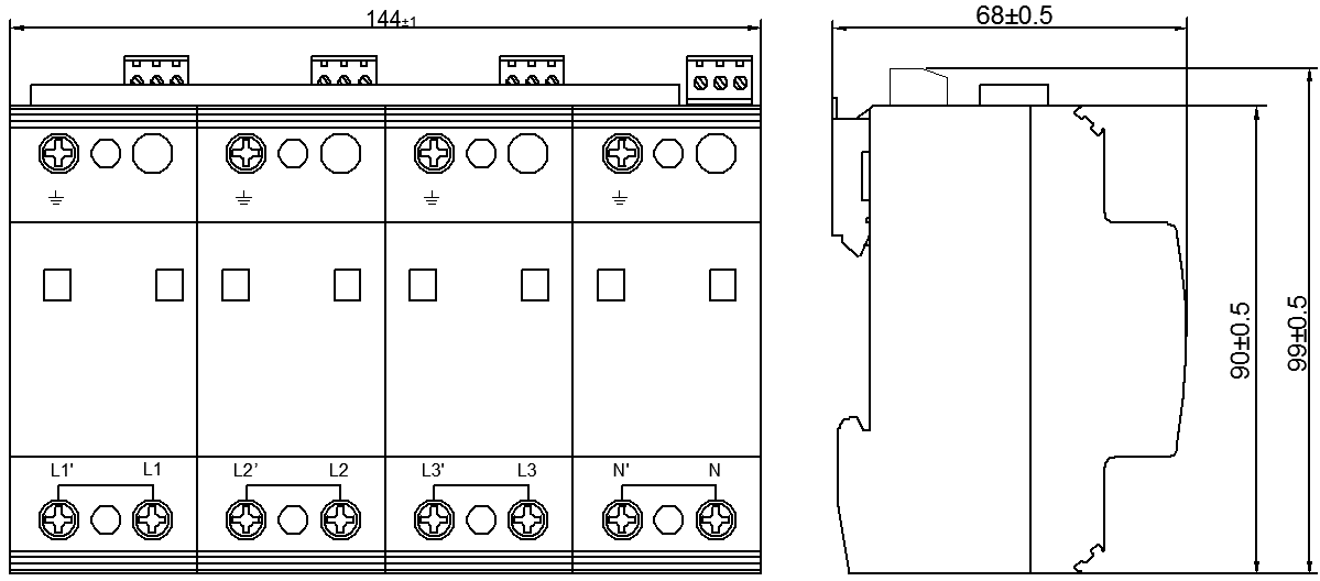
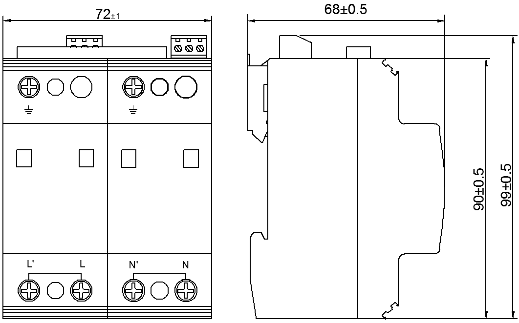
| Mounting on |
DIN 35 mm rail |
| Flammability |
UL 94 V-0 |
| Mode |
ZGG80-385(4+0)r |
ZGG100-385(4+0)r |
ZGG120-385(4+0)r |
| ZGG80-385(2+0)r |
ZGG100-385(2+0)r |
ZGG120-385(2+0)r |
| SPD according to IEC 61643-11 |
Class Ⅱ |
| SPD according to EN 61643-11 |
Type 2 |
| Protection mode |
L-PE, N-PE |
| Max. continuous operating voltage UC |
385 V |
| Operating frequency |
50/60 Hz |
| Nominal discharge current In (8/20μs) |
40 kA |
50 kA |
60 kA |
| Max. discharge current Imax (8/20μs) |
80 kA |
100 kA |
120 kA |
| Voltage protection level Up |
2.2 kV |
2.4 kV |
2.5 kV |
| Max. backup fuse |
250 A gL/Gg |
315 A gL/Gg |
400 A gL/Gg |
| Follow current interrupt rating Ifi |
100 Arms(N-PE) |
| Response time tA |
≤25 ns |
| Connection mode |
parallel |
| Cross-sectional Area |
tranded: 1.5 mm2~25 mm2, Solid: 1.5 mm2~35 mm2 |
| Max. Cross-sectional Area For Remote signalling terminals |
1.5 mm2 |
| Intensity of Remote Signalling Alarm Contact |
AC: 250 V/0.5 A 125 V/1 A DC: 30 V/0.1 A |
| Torque: Connecting Terminal/Remote Signalling Interface |
2.5 N•m /0.25 N•m |
| Degree of Protection (IP Code) |
IP 20 |
| Installation system |
TN-S |
| Mounting on |
DIN 35 mm rail |
| Flammability |
UL 94 V-0 |
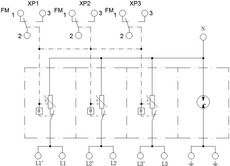
Circuit Diagram
3+1 Configuration
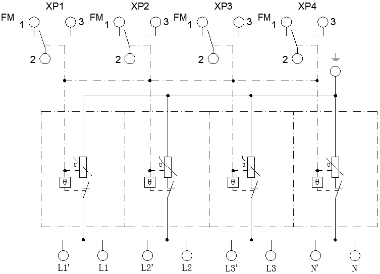
4+0 Configuration
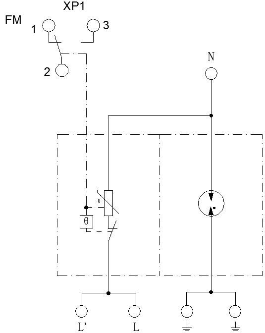 1+1 Configuration

2+0 Configuration
Configuration
3+1 Configuration
4+0 Configuration

1+1 Configuration
2+0 Configuration