|
Temperature range
|
-40 ℃~+85 ℃
|
|
Relative humidity range
|
5%~95% (+25 ℃)
|
|
Altitude range
|
-500 m~+3000 m
|
|
Model
|
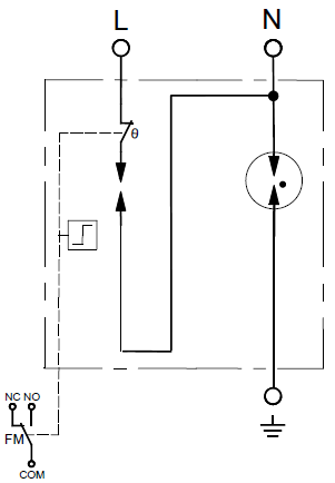
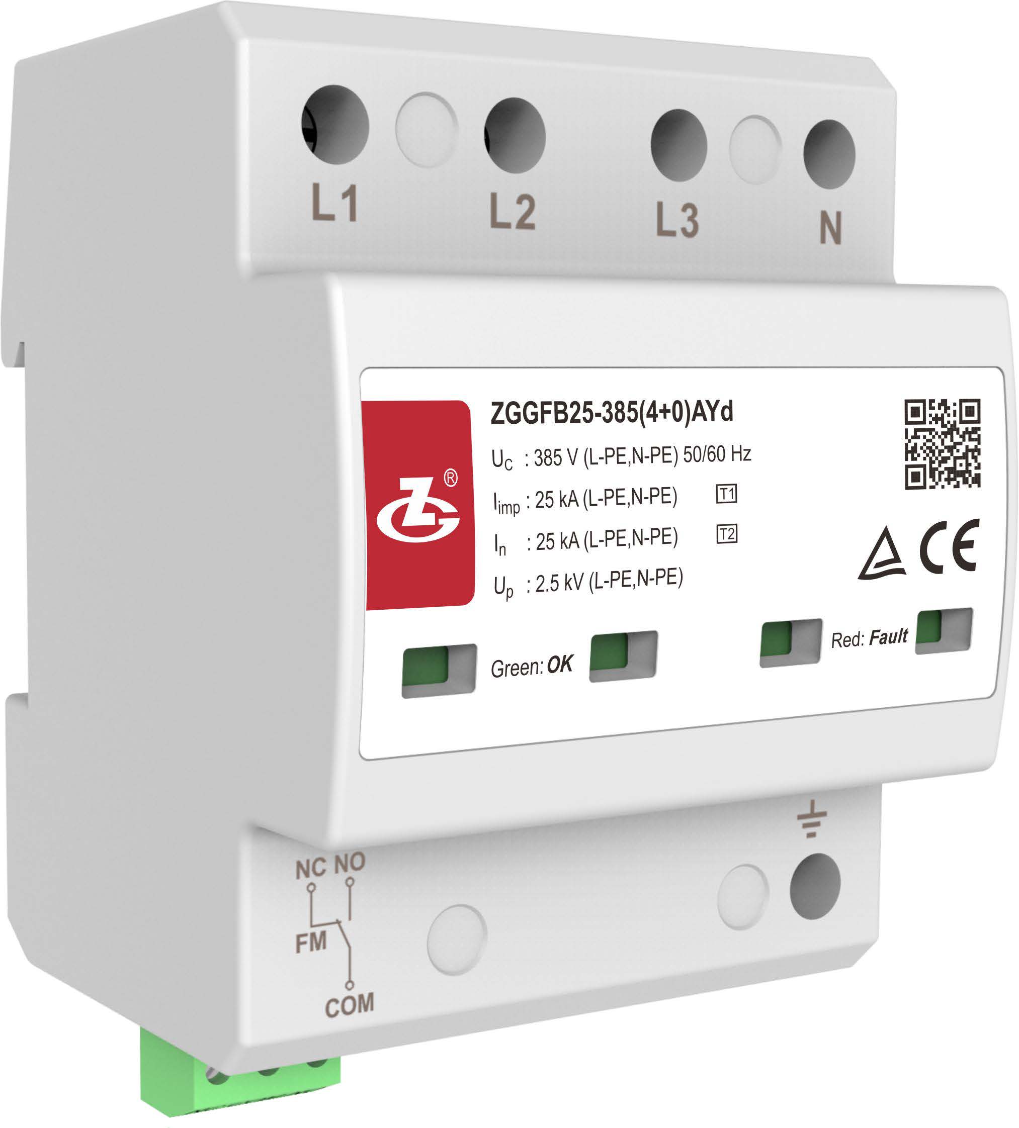
ZGGFB25-385(4+0)AYd
|
ZGGFB25-385(2+0)AYd
|
|
SPD According to IEC 61643-11
|
Class Ⅰ+ Class Ⅱ
|
|
|
SPD According to EN 61643-11
|
Type 1+Type 2
|
|
|
Number of ports
|
One port
|
|
|
Connection mode
|
In parallel
|
|
|
Grid voltage of the protected system
U0 (L-N phase voltage) |
230 V 50/60 Hz
|
|
|
Maximum continuous operating voltage (Uc)
|
385 V 50/60 Hz
|
|
|
Type of low voltage (LV) system
|
TN
|
|
|
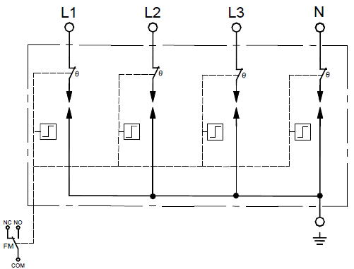
Modes of protection
|
L-PE, N-PE
|
|
|
Nominal discharge current In (8/20 μs)
|
25 kA
|
|
|
Impulse discharge current
Iimp (10/350 μs) |
25 kA
|
|
|
Quantity of electric charge(Q)
|
12.5 As
|
|
|
Specific energy (W/R)
|
156 kJ/Ω
|
|
|
Voltage protection level (Up)
|
2.5 kV
|
|
|
Measured limiting voltage UL( at Iimp)
|
≤1.0 kV (after 10 μs)
|
|
|
Follow current interrupt rating (Ifi)
|
3 kA (at 385 V a.c.)
|
|
|
Short-circuit current rating ISCCR
|
3 kA
|
|
|
Impulse withstand capability
(10/350 μs) |
12.5 kA (10 times, 5-minute interval)
|
|
|
Response time (tA)
|
≤100 ns
|
|
|
Leakage current
|
≤1 mA
|
|
|
Residual current (IPE)
|
≤1 mA
|
|
|
Transient overvoltage (TOV)
|
UT =442 V, tT =120 min
|
|
|
Application scenario
|
Indoor
|
|
|
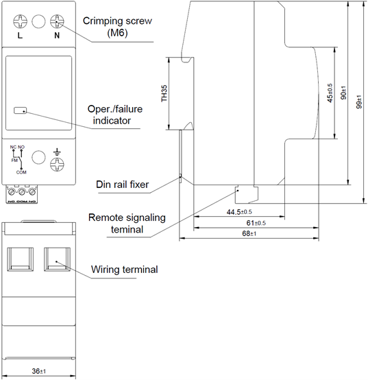
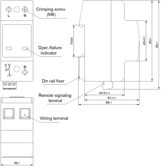
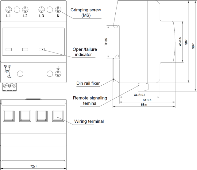
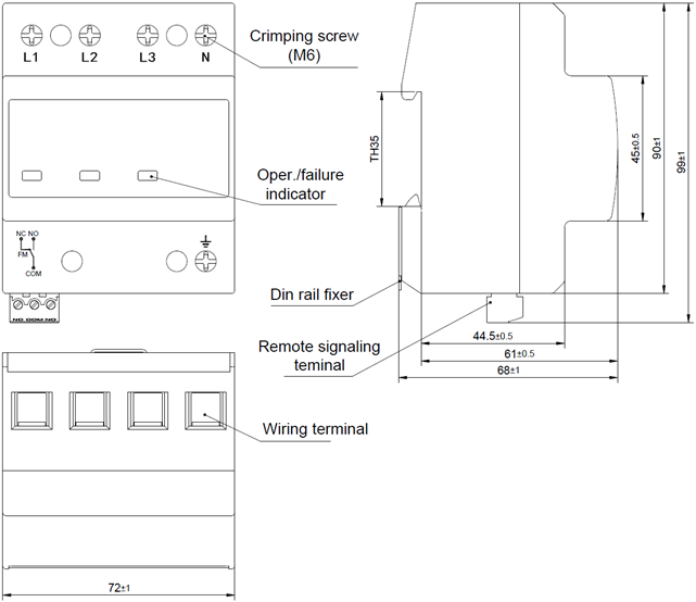
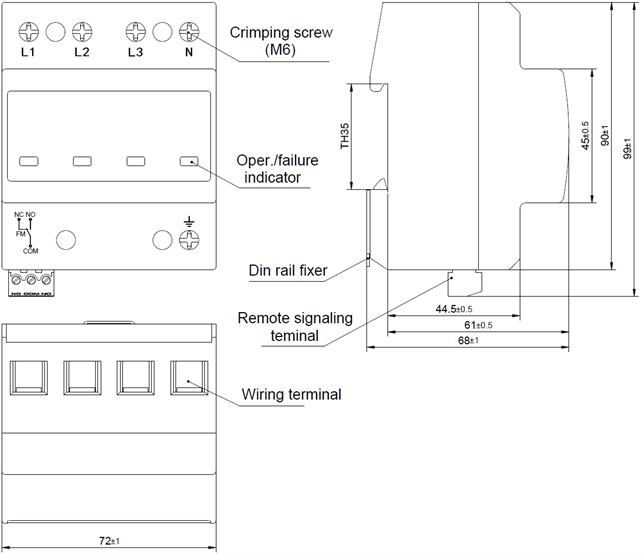
Installation method
|
35 mm DIN rail (Type TH 35, according to IEC/EN 60715)
|
|
|
Status Indication
|
Green: OK; Red: Fault
|
|
|
The cross-sectional area of the wire that can be clamped by the power supply terminal
|
6 mm2~25 mm2 multi-core wire
|
|
|
Torque: Terminal/Remote signaling interface
|
2.5 N·m/0.25 N·m
|
|
|
Remote signaling parameters
|
AC: 250 V/0.5 A, 125 V/1 A; DC: 30 V/0.1 A
|
|
|
The cross-sectional area of the wire that can be clamped by the remote signaling interface
|
0.5 mm2~1.5 mm2
|
|
|
Storage period
|
2 years
|
|
|
Guarantee period
|
2 years
|
|
|
Model
|
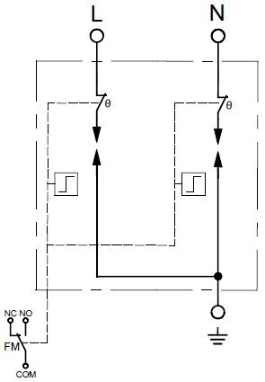
ZGGFB25-385(1+1)AYd1
|
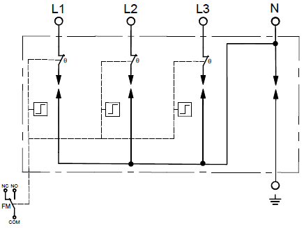
ZGGFB25-385(3+1)AYd1
|
ZGGFB25-385(3+1)AYd
|
|
SPD According to
IEC 61643-11 |
Class Ⅰ+ Class Ⅱ
|
||
|
SPD According to
EN 61643-11 |
Type 1+Type 2
|
||
|
Number of ports
|
One port
|
||
|
Connection mode
|
In parallel
|
||
|
Grid voltage of the protected system U0 (L-N phase voltage)
|
230 V 50/60 Hz
|
||
|
Maximum continuous operating voltage (Uc)
|
385 V (L-N), 255 V (N-PE) 50/60 Hz
|
||
|
Type of low voltage (LV) system
|
TN, TT
|
||
|
Modes of protection
|
L-N, N-PE
|
||
|
Nominal discharge current
In (8/20 μs) |
25 kA (L-N), 50 kA (N-PE)
|
25 kA (L-N), 100 kA (N-PE)
|
|
|
Impulse discharge current
Iimp (10/350 μs) |
25 kA (L-N), 50 kA (N-PE)
|
25 kA (L-N), 100 kA (N-PE)
|
|
|
Quantity of electric charge (Q)
|
12.5 As (L-N), 25 As (N-PE)
|
12.5 As (L-N), 50 As (N-PE)
|
|
|
Specific energy (W/R)
|
156 kJ/Ω (L-N), 625 kJ/Ω (N-PE)
|
156 kJ/Ω (L-N), 2500 kJ/Ω (N-PE)
|
|
|
Voltage protection level (Up)
|
2.5 kV (L-N), 1.5 kV (N-PE)
|
||
|
Measured limiting voltage UL( at Iimp)
|
≤1.0 kV (after 10 μs ) (L-N)
|
||
|
Follow current interrupt rating (Ifi)
|
3 kA (at 385 V a.c.) (L-N)
0.1 kA (at 255 V a.c.) (N-PE) |
||
|
Short-circuit current rating ISCCR
|
3 kA(L-N)
|
||
|
Impulse withstand capability (10/350 μs)
|
12.5 kA (10 times, 5-minute interval)(L-N)
|
||
|
Response time (tA)
|
≤100 ns
|
||
|
Leakage current
|
≤1 mA
|
||
|
Residual current (IPE)
|
≤1 mA
|
||
|
Transient overvoltage (TOV)
|
UT =442 V, tT =120 min (L-N)
UT =1200 V, tT =200 ms (N-PE) |
||
|
Application scenario
|
Indoor
|
||
|
Installation method
|
35 mm DIN rail (Type TH 35, according to IEC/EN 60715)
|
||
|
Status Indication
|
Green: OK; Red: Fault
|
||
|
The cross-sectional area of the wire that can be clamped by the power supply terminal
|
6 mm2 to 25 mm2 multi-core wire
|
||
|
Torque: Terminal/Remote signaling interface
|
2.5 N·m/0.25 N·m
|
||
|
Remote signaling parameters
|
AC: 250 V/0.5 A, 125 V/1 A; DC: 30 V/0.1 A
|
||
|
The cross-sectional area of the wire that can be clamped by the remote signaling interface
|
0.5 mm2 to 1.5 mm2
|
||
|
Storage period
|
2 years
|
||
|
Guarantee period
|
2 years
|
||