General
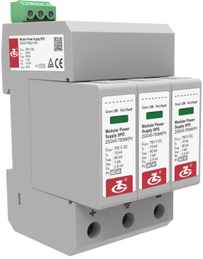
The ZGG40-1500(2+1)PV Modular Power Supply SPD is connected in parallel with the DC power system or photovoltaic system, which can be used to implement the second stage inverter protection. The module uses the MOV as a inside protective element, and it can be disconnected in a safe way to prevent overheating and overcurrent, to ensure that when the product fails, the DC arc can be safely off, without any burning and other accidents. In the absence of a surge, SPD has a high impedance, and when there is an overvoltage surge current, SPD will present ≤25ns response speed and continuous impedance decreases, thus the voltage across the SPD can be limited to a low level, thereby preventing lightning overvoltage (direct lightning overvoltage, overvoltage induced by lightning, etc.), switching overvoltage (any overvoltage generated by switching of electrical device, failure to start, and interruption) and temporary overvoltage (overvoltage generated by failure of low-voltage distribution system, activation of capacitors and start and stop of motors) damage to the equipment.
Features
1The modules are designed with the anti-reverse slot.
2High discharge capacity, low residual voltage,High safety and reliability.
3Overtemperature protection.
4Failure indication and remote signalling alarm dry contacts.
5Enclosure IP 20, UL 94 V-0.
Standards Complied
EN 50539-11:2013 Low-voltage surge protective devices - Surge protective devices for specific application including d.c. - Part 11: Requirements and tests for SPDs in photovoltaic applications
Technical Data
Operating Environment
| Ambient temperature |
-40 ℃~80 ℃ |
| Relative humidity |
5 %~95 % |
| altitude |
-500 m~﹢4000 m |
Technical Parameters
| Model |
ZGG40-1500(2+1)PV |
| SPD according to EN 50539-11:2013 |
Type 1;Type 2 |
| Overload behaviour mode |
OCM |
| Max. continuous operating voltage UCPV |
1500 V DC |
| Rated short circuit current ISCPV |
1 k A |
| Nominal discharge current In (8/20 μs) |
15 kA |
| Max. discharge current Imax (8/20 μs) |
40 kA |
| Impulse current Iimp(10/350μs) |
1 kA |
| Voltage protection level Up |
4.5 kV |
| Connection mode |
parallel |
| Protection mode |
+ — -、+/- —PE |
| Response time tA |
≤25 ns |
| Cross-sectional area for connection terminals to connect copper wires |
Stranded: 1.5 mm2~25 mm2, Solid: 1.5 mm2~35 mm2 |
| Max. cross-sectional area for remote signalling terminals |
1.5 mm2 |
| Intensity of remote signalling alarm contact |
AC: 250 V/0.5 A 125 V/1 A DC: 30 V/0.1 A |
| Torque: connecting terminal/remote signalling interface |
2.5 N•m /0.25 N•m |
| Degree protection provided by enclosure (IP code) |
IP 20 |
| Mounting on |
DIN 35 mm rail |
| Application system |
Photovoltaic system |
| Dimensions |
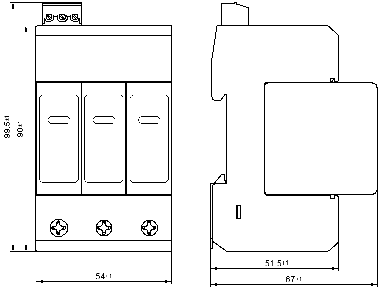
90 mm×54 mm×67 mm
(excluding remote signalling terminals) |
| Mounting on |
DIN 35 mm rail |
| Flammability |
UL 94 V-0 |
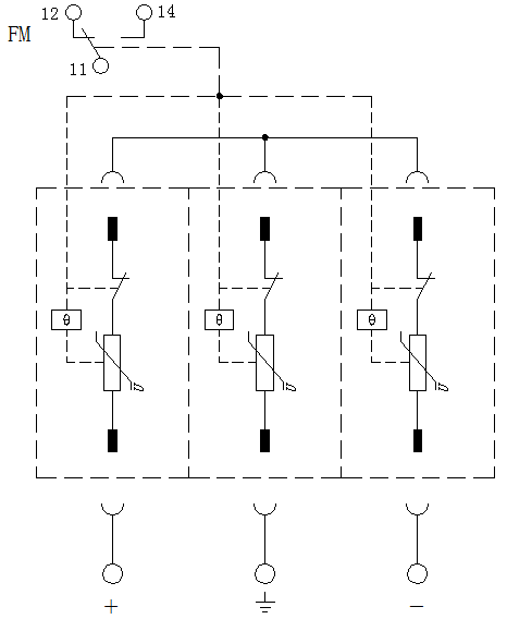
Circuit Diagram
Configuration


